The two RCA jacks, J2 and J3, are the outputs. J2 is the "Low Frequency", or integrated signal, and J3 is the "High Frequency", or non-integrated signal outputs. Both outputs have a ~+-10 volt output swing. They can drive over 100 feet (30m) of 50 or 75 ohm coax cable, and, drive resistive loads down to 600 ohms.
The connector J6 is used to supply +5 VDC power to the oscillator on the pendulum and the output drive signal to the damping coil. This connector has the following pinout:
	Pin 1		Damping coil output.
	Pin 2		Ground for dampening coil.
	Pin 3		+5 volts DC output.
	Pin 4		Ground for +5 volt output power.
The connector is a 4 pin .156 Molex connector. You should have received the mating hood and 4 pins with your board.
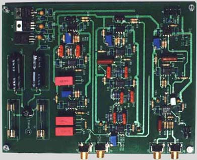
Gain Adjustment: There are two gain adjustment trim pots. R5 is the gain adjustment for the Low Frequency output port, and the other, R41, is for the High Frequency output port. A note about R41: It is possible to reduce the gain all the way down to zero. If you reduce the gain too much, you will not get the full +- 5 volt (or +-10 volt if you are using another A/D card other then mine) output swing needed for a full scale input to the A/D card. This will reduce your overall dynamic range. After setting the High Frequency gain pot to an reasonable level, you should excite the sensor to make sure you can saturate (+- 2047 counts with a 12 bit A/C card or +-32767 counts with a 16 bit card) your input to the A/D card. The Low Frequency gain adjustment, R5, can not be reduced to zero, so you should not run into this problem with it.
Damping Adjustment: This pot is marked R55. It is used to adjust the level to damping signal applied to the damping coil. If you can not reduce the gain enough for proper damping you will need to place a resistor in series with the one of the damping coil signal wires. A 4.7k 1/4 watt 5% resistor is a good starting point.
DC Offset Adjustment: The two pots, marked R7 and R31, are used for DC offset adjustment for each output channel. R7 is the Low Frequency channel's adjustment, and R31 is for the High Frequency channel. I have set the DC offset to 0 for both channels so you shouldn't need to adjust these pots.
A note about Rev-A of the board: The silk-screen artwork did not have the labels, other then the R numbers, for the five pots. I have marked the top of the Gain pots with a "G", the damping pot has a "D" marked, and the offset pots are marked with a "O".
The tilt LED was an after thought, and is located in the wrong location if you place the board in a box. If you do, then I would unsolder the LED and mount it on the front panel and add some wires to where the LED was solder to.