Last Updated: 12/17/99
The page describes the method I use to adjust the damping on my SG sensors.
You will need the following:
Some sort of coil. I use the coil from a relay, or you can wind one. It should have 1000
turns or more of any small wire size. The coil must not have any magnetic material, just
the bobbin and the wire. Attach enough wire to the coil, speaker wire will work fine, so
you can do the damping testing way from the sensor. You will also need a DC power supply
or battery, and some way of viewing the data. You can use your SDR
or EMON system, or, you can also use a storage scope if you have access to one.
After setting up the sensor, mount the coil behind, or on the end of, the normal damping coil used by the sensor. You can use some tape or other sticky substance (I use something called "Stik Tak" available a hardware store) to hold the coil on the end of the sensors damping coil.
The best thing to do is run your data logging system in another room so you will not disturb the sensor. Run the wire from the damping adjustment coil into the other room and connect up one end to the power supply. You will be temporarily connecting the other wire to the power supply or battery to excite the pendulum.
After covering the sensor and letting it settles down, your ready too go. Start with the Damping Adjustment trim pot (R55) set to minimum. Minimum is when you turn the pot counter clockwise until you can hear a click.
Set your data logging software to an X scale of 1 so that you can see what happens when you excite the pendulum.
Now quickly touch the second wire to the power supply or battery. You will need to experiment with the voltage of the power supply or battery and how long you touch the wire to it. One thing you can do is charge up a electrolytic capacitor and discharge it through the coil. A 10uf / 25V cap should be a good starting value. It is important not to saturate the sensor by exciting the pendulum too much. You can control the amount of movement by varying the voltage to the excitation coil or the amount of time you connect the coil to the power supply or battery.
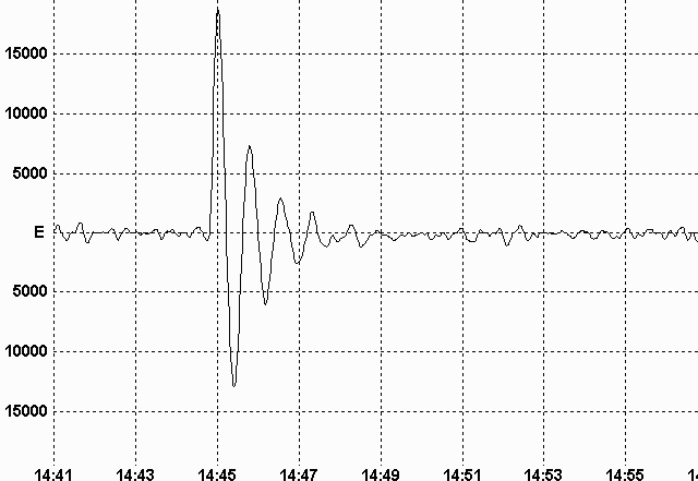
Using the three WinQuake screen shots below as a reference, adjust the Damping Adjustment trim pot so that it matches the second screen shot.
Note that it takes several cycles for the signal to die down.
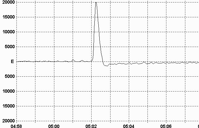
Note that there is no, or very little, undershoot in the negative direction.
If you have too much damping with the trim pot turned to minimum, you will need to add a resistor in series with the coil. With the trim pot all the way to minimum add enough resistance so that the system becomes under damped. Then use the trim pot to adjust the damping to the proper point.
If you can't get enough damping with the trim pot all the way to maximum then you will need to do the one, or a combination of, the following:
Reduce the weight of the pendulum.
Add more turns of wire to the damping coil.
Get a stronger damping magnet.