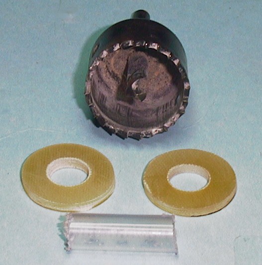
The coil bobbin is made from a piece of stiff plastic tubing about 1 and 1/4 inches long with a inside diameter of 3/8 inches. The sides of the bobbin are made out of PC board material with the copper removed. The photo below shows the drill I use to make the two bobbin sides.
The inside holes are then filed so that the tube will fit snugly inside the bobbin sides. I then glue the sides to the tube, spacing the sides about 1 inch apart. After the glue dries, I wind a few hundred turns of small wire on the bobbin. The coil resistance should be around 100 to 200 ohms.
The transmitter and receiver plates are made from double sided PC board material. The receiver plates are square, they can be anywhere from 1 inch to 2 inches in size. For the transmitter plate, I first make it rectangular with one side a little larger (~1/2 inch) then the receiver plates. I then cut out a tab in the middle that is used to hold the transmitter plate onto the boom. See drawing below:
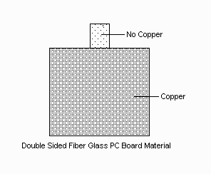
After cutting the tab out, I etch off the copper on the tab. You can also use a file or knife to remove the copper. The transmitter plate is then mounted to the boom and the oscillator is then place on the end of the boom near the transmitter plate. Using two small wires, I solder them to each side of the plate a the top near the tab. I then solder the other end of the wires to the output of the oscillator. These wires should be as short as possible.
The two receiver plates are also made from double sided PC board material and cut to the same size as the transmitter plate, excluding the mounting tab. After cutting the plates I use a fine file at a 45 deg angle and file away the copper on all 8 sides of each plate. This is to insure that there is no short between the two copper sides of the plate. To mount the receiver plates to the base plate of the sensor I use solid brass (make sure that the material is non magnetic) "L" brackets 1 x 1 x 1/2 (width) inches in size. The receiver plates are placed about 1/2 inch above the base plate.
To isolate the ground of the sensor and the ground side (the side not facing the transmitter plate) of the receiver plate, I use a washer or spacer made from double sided PC board material. The washer/spacer is cut square the same width as the "L" bracket. One side is supper glued to the "L" bracket and the other to the receiver plate. Using an ohm meter I then check that there is no conductivity between the receiver plate and the "L" bracket. Make sure that you mount the two receiver plates the same height above the sensor's base plate.
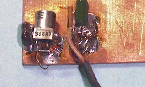
Using the schematic and photos below mount and wire the parts on the receiver plate. Both plates are made identical except the diode is reversed on one of the plates.
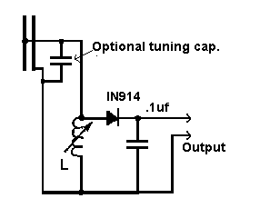
Note: 1N914 diode is reversed on second receiver.
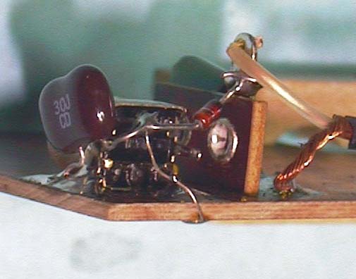
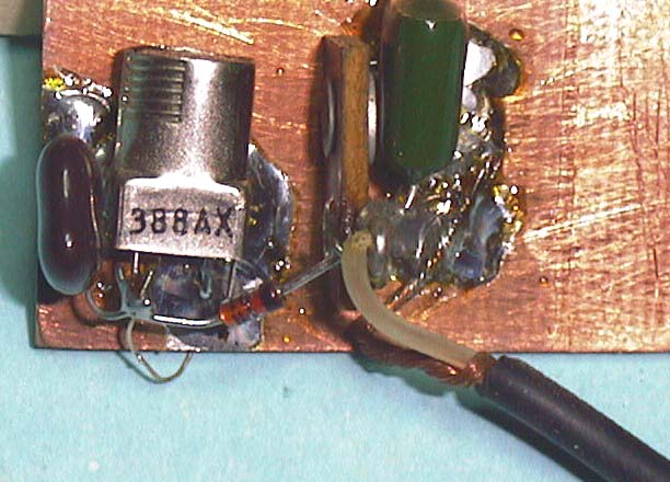
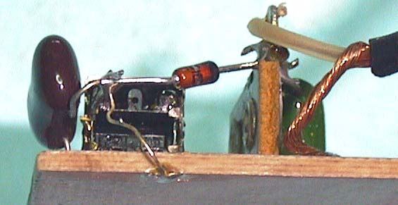
Note small wire soldered to the junction of the coil/diode/optional cap and the other side of the receiver plate.
For information on tuning the receiver plates see this page.
Good luck....